here is the new smaller but longer wire. Running at 6 volts the pull in is very fast. The Muscle wire's reaction time is down to less that a quarter second. Unfortunately, the RF module has added a half second. We're still better than we were on response time.
notice the "basic stamp" prototyping computer to left of wires.
and here is the RF Transiever. on/off AND serial DATA!
And now (drum roll please) may I present..............
Right (wire) side, all assembled with battery in place.
Left (electronics) side, all assembled
View from the butt, battery in place. Note LED light at butt on bottom (electronics) side, and buzzer on top (wire) side. Buzzer is mounted to the battery holder.
View from trigger guard side, battery removed
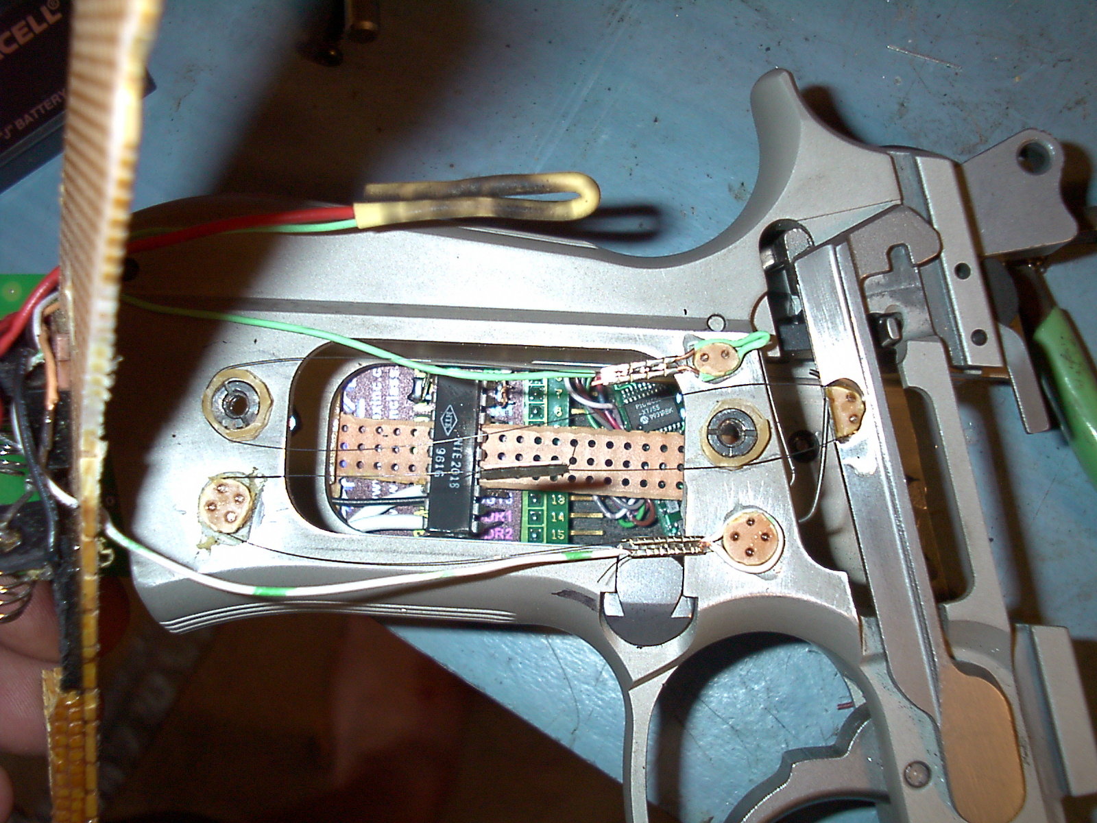
Left (electronics) side with grip layer and RF Transceiver removed. Basic Stamp and Driver chip are in place. Note how driver chip takes advantage of the space where the handle is cut away (you are seeing the bottom of the driver chip here.)
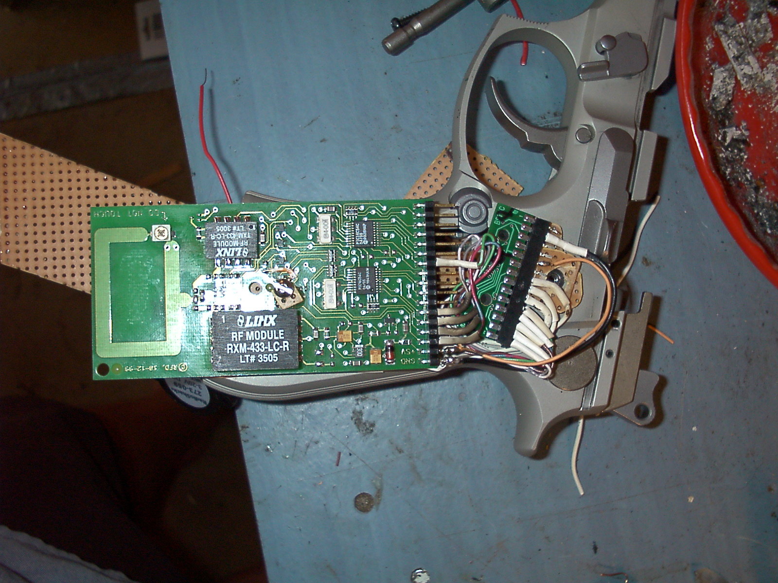
Left (electronics) side with only grip layer removed. RF Transceiver, Basic Stamp, and Driver chip are in place. (driver chip is covered by the RF module here.)
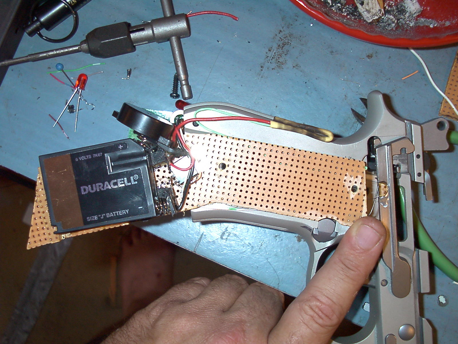
Right (wire) side with grips only removed. Battery in place. This is a protective layer over the muscle wire, as well as a good anchor for the battery holder.
Right (wire) side with grips and protective/battery layer removed to expose muscle wire. Note top of driver chip and Basic Stamp visible from right (electronics) side through hole.
Well, that's it! I'll let you know when the software is ready.